

3×5 Floor Standing LCD Video Wall for Energy Control Rooms
Description
Why a Floor Cabinet Fits Utility Control Rooms
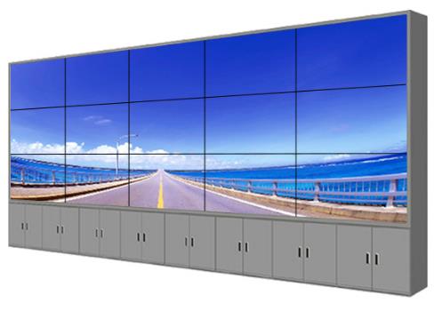
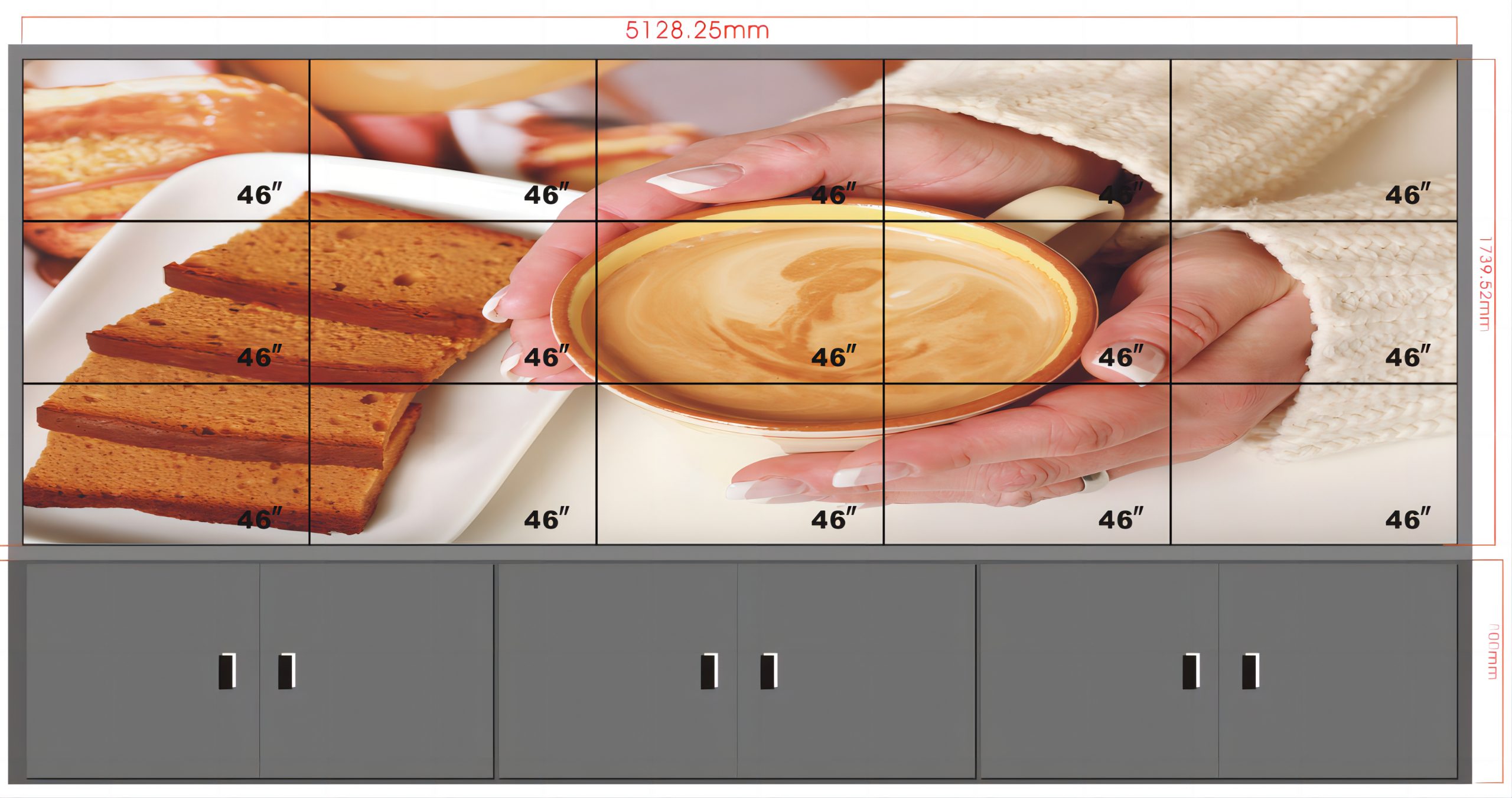
Utility operators benefit from a stable system diagram surrounded by supporting evidence. A 3×5 floor standing LCD video wall for energy control rooms combines 15 panels arranged in 3 rows and 5 columns, giving power, water, HVAC or campus-energy operations teams room for network status, long trends and station video.
The normal source list includes single-line diagrams, equipment status, load trends, fault records, site video, work orders and shift information. Historical trends may run continuously while high-priority faults need an immediate, larger position, so window behavior should be defined before controller selection.
Reserve the Middle Columns for the Network Diagram
The proposed composition follows the central three columns for the main system diagram and the outer columns for trends, alarms and site video, switching to fault analysis and dispatch coordination during an incident. This keeps the network or process overview steady while side zones change between load, fault and maintenance information.
A 3×5 floor standing LCD video wall for energy control rooms should never force an operator to choose between an alarm and the trend needed to understand it. Presets can protect permanent zones and expand diagnostic evidence temporarily.
Compare Front Service with Rear-Aisle Maintenance
A floor cabinet can be designed for front access, rear access or a combination. Rear service offers direct cable visibility but consumes room depth; front service protects space behind the wall but requires reliable movement and safe panel handling.
The customer should choose after reviewing the room plan and maintenance practice. Decorative doors or trim must not block the selected service method.
Manage Heat from Panels and Processing Equipment
Fifteen panels, distribution equipment and processors create a continuous thermal load. Calculate ventilation for the complete cabinet volume and verify that hot air does not recirculate into upper panels.
Temperature should be measured during sustained operation with the cabinet closed. An attractive enclosure is not acceptable if normal service requires doors to remain open.
Prepare for Future Utility Sources
Energy control rooms often add substations, meters or analytics platforms after initial deployment. Reserve defined input and network capacity for likely expansion instead of leaving every future connection to temporary converters.
Expansion planning should still have a limit. Record available ports, supported resolutions and the method for adding a new window so future work does not disturb approved layouts.
Route Power and Signals Through a Maintainable Base
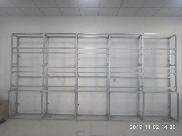
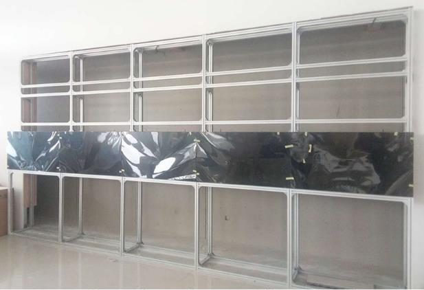
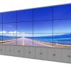
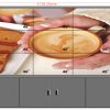
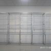
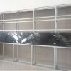
The gallery shows a floor-supported cabinet, which changes the site survey. The frontend images show a floor-standing cabinet structure, so floor loading, cabinet leveling, bottom cable entry, heat-removal paths, service doors and anti-tip anchoring must be checked. Floor openings and anchors must be ready before the cabinet arrives.
Leveling begins at the base because a small cabinet error becomes visible across five columns. Internal ventilation, service doors and cable bend radius should be inspected before panels close the front.
Balance Continuous Trends with Alarm Detail
Signal design should distinguish permanent engineering workstations from occasional meeting or maintenance laptops. The 3×5 floor standing LCD video wall for energy control rooms needs enough outputs for fifteen panels, but input and window capacity follows the utility workflow.
Arrange power and processing so a single local fault does not remove every operating view. Screen labels, one-line diagrams and a recorded startup sequence shorten troubleshooting.
Inspect Thermal and Service Conditions Under Load
Thermal and operational acceptance should happen under realistic load. complete acceptance using long-duration trends, rapid alarms, cross-screen system diagrams, mapping of all 15 outputs, cabinet temperature-rise checks and single-panel removal clearance. Trend lines, alarm flashes and cross-screen diagrams reveal problems that static photographs do not.
The final record for the 3×5 floor standing LCD video wall for energy control rooms covers cabinet anchoring, internal temperature, mapping, color balance, panel removal and the recovery procedure used by the control-room team.
Site Data for a Floor-Cabinet Proposal
A floor-cabinet proposal needs dimensions for the room, door and delivery route as well as floor load, anchor locations, bottom cable openings, rack position, operator distance and rear or front service clearance. Confirm whether cabinets arrive assembled or in sections.
The supplier can then define the structure, panel size, processor, internal distribution, ventilation, trim and spare strategy for the 3×5 floor standing LCD video wall for energy control rooms. Factory assembly drawings should be approved before the site base is prepared.
Frequently Asked Questions
How many panels are included?
A 3×5 configuration uses fifteen panels arranged in three rows and five columns.
Why choose a floor-standing cabinet?
It provides independent structural support, organized bottom cable entry and a finished equipment enclosure where the wall cannot carry the load.
Can the wall show trends continuously?
Yes. Assign permanent trend zones and allow temporary incident windows to expand without hiding critical alarms.
What floor information is required?
Confirm load capacity, level tolerance, anchoring points, cable openings and the route used to move cabinets and panels into the room.


Inquiry
You must be logged in to post a review.
Related products
-

1×2 LCD Video Wall for Compact Control Rooms
Why Two Screens Work in…
-

4×1 Vertical LCD Video Wall for Broadcast Studios
Build a Clear Production Hierarchy…
-
6×4 LCD Video Wall for Traffic Management Centers
Combine Road Networks and Junction…
-
2×4 LCD Video Wall System for Surveillance Centers
Eight Panels for a Clear…
Reviews
There are no reviews yet.