


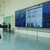
4×8 LCD Video Wall for Railway Operation Centers
Description
Expand Railway Status across Thirty-Two Panels
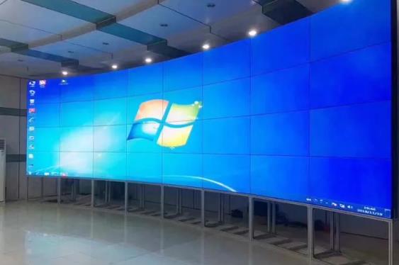
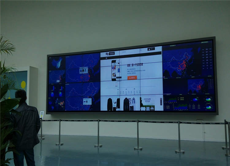
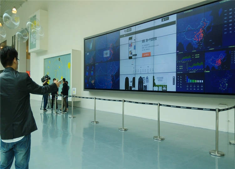
A 4×8 LCD video wall for railway operation centers offers a broad canvas for line diagrams, stations, train positions, power, communications, video and incident information. Eight columns accommodate a long route while four rows leave room for affected sections, alerts and conferences.
Keep the primary line diagram in a stable location so dispatchers build spatial familiarity. Cameras and detailed data can appear when an event requires them, while individual workstations retain fine control and record entry. The shared line picture also supports shift handover because the incoming team can see current restrictions and priorities.
Create Operating Modes for Normal, Disrupted and Maintenance Work
Normal mode emphasizes timetable and line health, disruption mode enlarges the affected section, alternatives and resources, and maintenance mode presents possession areas, work windows and safety confirmation. Scene names should follow the established dispatch process.
After a change, the event number, time and responsible role remain visible. If several events run simultaneously, primary and secondary areas need defined escalation rules so one window cannot unintentionally cover the full operating picture. Mode ownership should be documented so maintenance and dispatch teams cannot unintentionally recall conflicting wall scenes.
Protect a Long Line Diagram from Eight-Column Bezels
Station names, train identifiers, signal states and distance markers should not fall on vertical joints. The route line may continue across panels, but critical nodes stay inside safe zones and affected sections can be enlarged through presets rather than improvised dragging.
Use consistent symbols with text or shapes in addition to color. The 4×8 LCD video wall for railway operation centers should make abnormal location and direction visible at the rear, while detailed logs and dense tables remain at close workstations. A full-size test image should use real station-name lengths and the symbol density expected during disruption.
Align Time across Train, Power, Communications and Video
Railway information comes from several platforms, and time differences can affect dispatch and review. Wall sources should use a common time reference and display their update time, origin and connection condition.
Standardize station, section and equipment names across systems. Access to operation control, work planning, video and conference sources should follow role permissions, remote-access policy and audit requirements. Disconnected sources need a visible state so an old train position or equipment condition cannot appear current.
Zone Power, Signals and Service Paths
Divide power, signals and cooling so a single node cannot remove the entire canvas. The primary line diagram may use an alternate source or validated emergency page, while redundancy for control components follows the required recovery time.
The support structure must control accumulated alignment across eight columns and allow individual-panel service. Use one coordinate convention for screens, ports and cables, then restore mapping, presets, time and permissions after maintenance. Zone recovery should be tested in the order that technical staff are expected to follow during an operating shift.
Commission through a Railway Disruption Exercise
Simulate a section fault or train delay from detection and confirmation through operating adjustment, conference and recovery. Verify that the line, train positions, station states, communications and timeline change correctly with each stage.
Test one failed data feed, lost camera and control restart. Acceptance of the 4×8 LCD video wall for railway operation centers should involve dispatch, technical and maintenance roles so the recovery method matches real shift practice. The exercise should include the transition back to normal service because unresolved temporary layouts can create later confusion.
Prepare the Route and Interface Schedule for Quotation
Provide room dimensions, consoles, sightlines, line-diagram scope, connected systems, source counts and formats, operating hours, conferencing, racks and network-security conditions.
Add continuity goals, installation windows, redundancy expectations and the acceptance scenario. A complete schedule defines display, processing, control, structure, cabling, commissioning and training and makes proposals comparable. For a 4×8 LCD video wall for railway operation centers, route and interface records provide the basis for a controlled deployment.
Frequently Asked Questions
Can the wall show one complete long railway line?
Yes. The eight-column canvas suits a long route, provided station names and critical states respect bezel safe zones.
Can train positions and video appear together?
Yes. The line diagram may remain primary while related video opens in an event zone.
How is time kept consistent across systems?
Use an agreed time source and show data update status; the exact method depends on the connected platforms.
Will one control failure disable the entire wall?
The impact depends on architecture; zones, alternate inputs or redundant control can reduce risk against a defined recovery target.
Inquiry
You must be logged in to post a review.
Related products
-

1×3 LCD Video Wall for Retail Wayfinding Systems
Turn Three Horizontal Panels into…
-

4×1 Vertical LCD Video Wall for Broadcast Studios
Build a Clear Production Hierarchy…
-
3×9 LCD Video Wall for Executive Briefing Centers
Create a Shared Evidence Wall…
-
5×1 Vertical LCD Video Wall for Transport Terminals
Present Five Levels of Travel…
Reviews
There are no reviews yet.