


49 Inch 4×6 LCD Video Wall for Airport Operations
Description
Build an Airport-Wide Picture with Twenty-Four Panels
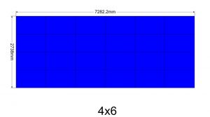
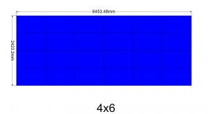
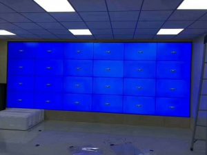
A 4×6 arrangement combines twenty-four 49-inch displays for flight movements, stand status, baggage handling, weather, security and facility information. Six columns can extend an apron or terminal view, while four rows preserve clear zones for alarms, video and joint briefings.
The wall should support decisions rather than show every source permanently. Routine duty keeps flight and critical facility status visible; weather, equipment or security events then enlarge the affected area, cameras and resources so different teams work from one operational picture. As a 49 inch 4×6 lcd video wall airport operations center display, the canvas keeps flight and facility decisions visible across duty teams.
Save Presets for Each Airport Operating Condition
Normal traffic, peak operations, severe weather, equipment faults and joint coordination require different source combinations. Approved presets hold the main view, supporting windows and alarm positions, avoiding improvised window movement during a fast-changing event.
Every transition should retain the incident number, update time and responsible desk. Operators recall protected scenes while administrators maintain inputs and layouts, reducing the chance that an accidental whole-wall change disrupts the airport operations center. A scene register should also identify the approved owner, activation condition and normal layout that follows each operating mode.
Keep Flight Tables and Stand Maps Clear of Bezels
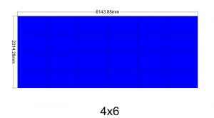
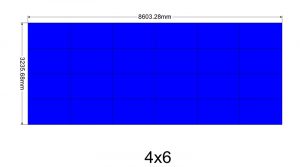
A four-row, six-column grid creates many bezel intersections. Flight numbers, gates, stand identifiers, times and alarm text belong inside safe areas. Maps may cross multiple panels, but essential labels and digits should never sit on a joint.
Acceptance templates should use the longest real flight fields, airport-area names and approved status colors. Test text from the farthest console and check maps and video from both side positions before approving the full canvas. Templates for the 49 inch 4×6 lcd video wall airport operations center display should include edge-console photographs as part of visual approval.
Align Time across Flight, Security and Facility Systems
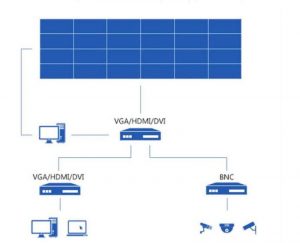
Airport platforms refresh at different rates, so each displayed source should identify its origin, update time and connection state. Flight information, video, baggage, access control and facility alarms need a common time reference for response and later review.
Access should also be layered. Sensitive video, personal information and controls remain limited to authorized roles; visitor scenes use masked layouts, and remote support reaches only the device status and logs required for maintenance. A common data dictionary prevents different departments from using conflicting stand, gate or terminal names during the same incident.
Plan Zoned Maintenance and Recovery
Structure, power, signals and cooling should be divided into service zones so local work does not remove the complete flight and incident overview. Critical pages can use an alternate input or validated emergency image with a documented changeover and recovery order.
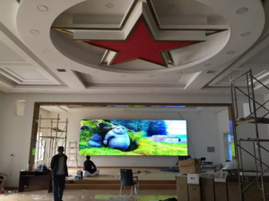
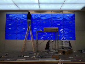
Use one coordinate scheme for panels, cables, processor outputs and rack ports. After replacement, verify source mapping, time, scenes and permissions in addition to image presence, preventing a technically active wall from showing information in the wrong position. Recovery planning for the 49 inch 4×6 lcd video wall airport operations center display should define the minimum view required during maintenance.
Accept the System through a Flight Disruption Exercise
Commissioning can simulate weather-driven delays from initial notice and impact confirmation through stand changes, passenger communication and recovery. Check preset recall, data updates, conferences, synchronization, color consistency and readability from edge consoles.
Also test one lost data source, a processor restart and the fallback page. Operations, security, facilities and engineering teams should approve the results, scene register, topology, access matrix and escalation procedure together. The exercise report should record unresolved interface issues and assign them before the system enters routine airport service.
Prepare the Airport System and Site Inventory
Provide room dimensions, console locations, viewing distances, connected platforms, source formats, simultaneous windows, operating hours, racks, power, network and supporting structure. State the desired redundancy, service direction, installation window and acceptance scenario.
These inputs define displays, processing, control, mounting, transmission, spares, commissioning and training. A complete inventory makes proposals comparable without substituting generic assumptions for unconfirmed airport interfaces. Complete site records allow the 49 inch 4×6 lcd video wall airport operations center display to be quoted against verified operating requirements.
Frequently Asked Questions
How many panels are used in a 4×6 layout?
The configuration uses twenty-four 49-inch panels arranged in four rows and six columns.
Can flight data and surveillance video appear together?
Yes. Processing can assign zones for flights, maps, video and alarms according to the confirmed inputs.
What happens when a data feed stops?
The approved design should show connection status, a last-update time or a fallback page rather than presenting old data as live.
Does one panel service require a full shutdown?
Zoned power, signals and service access can reduce the impact, but the actual scope depends on the final architecture.
You must be logged in to post a review.
Related products
-

2×1 Vertical LCD Video Wall for Retail Stores
Use Vertical Space for a…
-
5×5 LCD Video Wall for City Command Centers
Build a Shared City Picture…
-

2×3 LCD Video Wall System for Control Rooms
Six Panels for Continuous Monitoring…
-

5×1 Vertical LCD Video Wall for Transport Terminals
Present Five Levels of Travel…
Reviews
There are no reviews yet.